Anti-theft cramp ring

An anti-theft type, buckle technology, applied in the field of zippers, can solve the problems of easy theft and other problems, and achieve the effect of simple assembly operation, easy and accurate positioning, and accurate positioning

Active Publication Date: 2008-10-22
KEE (GUANGDONG) GARMENT ACCESSORIES LTD
View PDF1 Cites 0 Cited by
  • Summary
  • Abstract
  • Description
  • Claims
  • Application Information

AI Technical Summary

Problems solved by technology

But the defect of this structure is: in the terminal stores of clothes and purses equipped with the hook structure zipper, the decorative pull tab can be unloaded due to pressing the elastic movable piece, causing the decorative pull tab on the zipper, especially the one with the famous brand logo Decorative pull tabs are prone to theft

Method used

View more

Image

Smart Image Click on the blue labels to locate them in the text.
Viewing Examples
Smart Image
  • Anti-theft cramp ring
  • Anti-theft cramp ring
  • Anti-theft cramp ring

Examples

Experimental program
Comparison scheme
Effect test

Embodiment 1

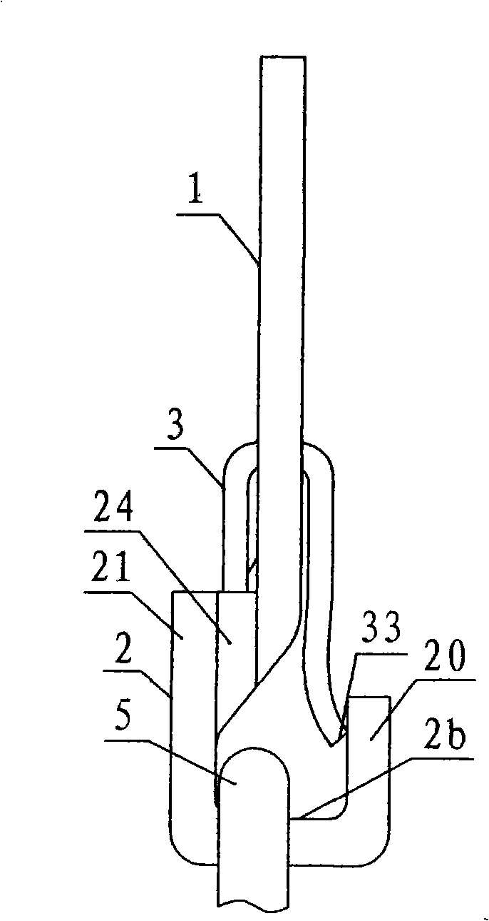
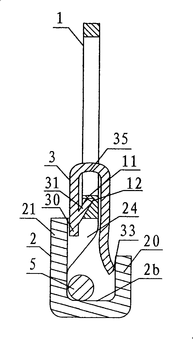
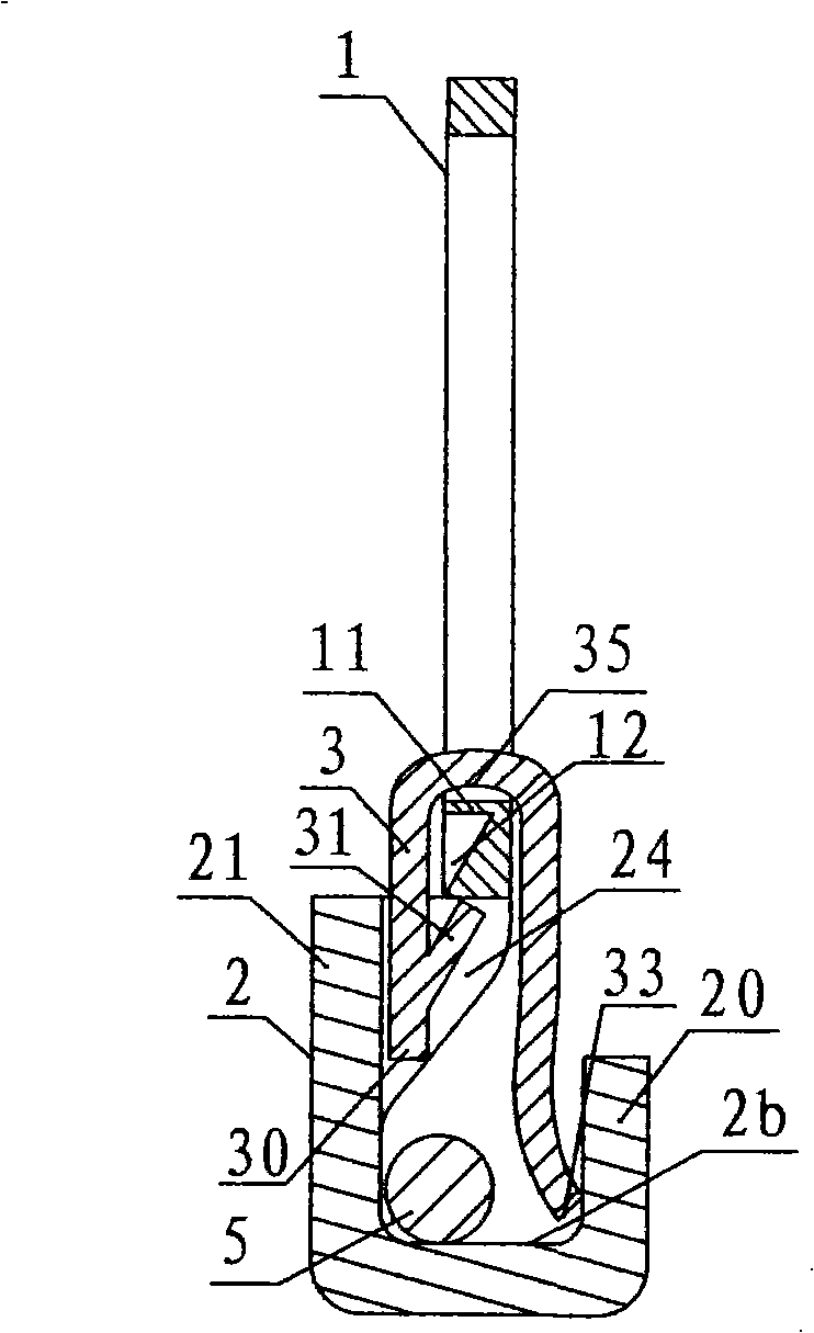
[0038] Such as figure 1 , 2 , Shown in 3, 4, 5, a kind of anti-theft buckle, comprises ring-shaped ring 1, hook 2, and U-shaped elastic piece 3. Such as figure 1 , 2 As shown, the wall-mounted end 21 of the hook 2 is relative to the suspension ring 1, and the wall-mounted end 21 of the hook 2 is below the ring wall portion 11 of the suspension ring 1, that is, there is an up-down dislocation structure between the two. Such as figure 1 , 2 As shown in and 5, the wall-mounted end 21 of the hook 2 is relative to the suspension ring 1, and the wall-mounted end 21 of the hook 2 is in front of the ring wall portion 11 of the suspension ring 1, that is, there is a front-rear misalignment structure between the two. Such as Figure 4 and Figure 5 As shown, the wall-mounted end 21 of the hook and the ring wall portion 11 of the suspension ring 1 are connected through the transition turning wall 24, and the wall-mounted end 21 and the ring wall portion 11 are connected due to the...

Embodiment 2

[0042] Such as Figure 6 , 7 As shown, on the basis of Embodiment 1, a first boss 32 is provided on the outer wall of the positioning end 30 of the elastic sheet 3, and a first boss 32 is arranged on the inner side of the wall-mounting end 21 of the hook 2 to connect with the first boss. The table 32 fits into the first groove 22 . Such as Figure 7 As shown, in the second assembly process, the elastic piece 3 is pushed downwards, so that the first boss 32 slides into the first groove 22, and the first boss 32 and the first groove 22 are fitted together. The elastic piece 3 is positioned at the position where the anti-theft buckle is in an anti-theft state.

Embodiment 3

[0044] Such as Figure 8 , 9 As shown, on the basis of the second embodiment, a second groove 23 adapted to the first boss 32 is provided inside the wall-hanging end 21 of the hook 2 and above the first groove 21 . In the first assembly process, while the elastic barb 31 is positioned at the positioning part 12, the first boss 32 is stuck in the second groove 23, and the first boss 32 and the second The cooperation between the grooves 23 plays an auxiliary positioning role for the first assembly position of the elastic piece 3 . Simultaneously, the distance between the second groove 23 and the first groove 22 also defines the distance that the elastic sheet 3 needs to be pushed down to make the anti-theft buckle in the anti-theft state. In addition, in order to facilitate the second assembly, the first boss 32 can smoothly slide into the first groove 22 from the second groove 23, and the second groove 23 can be transitioned to the first groove 22. Do some arc treatment on t...

Login to view more

PUM

No PUM Login to view more

Abstract

The invention discloses an anti-theft type snap ring which comprises an annular flying ring 1, a hook 2 and a U-shaped elastic trip 3. An end of hanging wall 21 of the hook 2 is fixedly connected with the external side edge of ring wall 11 of the flying ring 1 by a transitional inflection wall 24 arranged at the two sides of the end of the hanging wall 21 of the hook 2, an upward and downward misplacement structure and a forward and backward misplacement structure are formed between the end of the hanging wall 21 of the hook 2 and the ring wall 11 of the flying ring 1. The end of the hanging wall 21, the transitional inflection wall 24 and the ring wall 11 form a locating through hole 4 which adapts to the elastic trip 3. An locating end 30 of the elastic trip 3 is inserted into the locating through hole 4, an free end 33 of the elastic trip 3 is pressed at the inner side of a hook wall 20 of the hook 2, the inner side of the locating end 30 of the elastic trip 3 is equipped with an elastic barb 31, the ring wall 11 of the flying ring 1 is equipped with a locating part 12 which is correspondingly in a groove shape or a through hole shape. The structure of the anti-theft type snap ring leads producers and sellers to replace decorative zipper pulls by twice assembly and realizes guarding against theft in terminal shopping places, which is applicable to various snap ring structures.

Description

technical field [0001] The invention relates to the field of zippers, in particular to a buckle of a zipper. Background technique [0002] The decorative slider on the existing slide fastener is generally hung in the closed hook fixedly connected with the slider of the slider. For the convenience of manufacturers or sellers to replace the decorative pull tab, someone proposes a kind of elastic movable hook, such as Chinese patent application No. 98246785.0, named "zipper puller", which discloses a zipper puller, which is provided with an elastic movable hook, A normally closed elastic movable piece is arranged at the opening of the hook, and the decorative pull piece can be easily replaced by pressing the elastic movable piece. But the defect of this structure is: in the terminal stores of clothes and purses equipped with the hook structure zipper, the decorative pull tab can be unloaded due to pressing the elastic movable piece, causing the decorative pull tab on the slide...

Claims

Login to view more

Application Information

Patent Timeline
no application Login to view more
Patent Type & Authority Applications(China)
IPC IPC(8): A44B19/24A44B19/26
Inventor 许锡鹏
Owner KEE (GUANGDONG) GARMENT ACCESSORIES LTD
Who we serve
  • R&D Engineer
  • R&D Manager
  • IP Professional
Why Eureka
  • Industry Leading Data Capabilities
  • Powerful AI technology
  • Patent DNA Extraction
Social media
Try Eureka
PatSnap group products